


CNC stands for Computer Numerical Control. It's a technology that utilizes computers to control machine tools and automated manufacturing processes. This allows for precise and efficient production of complex parts and components. CNC machines operate based on programmed instructions (G-code).
CNC (Computer Numerical Control) is required in manufacturing for several key reasons:
G-code is a standardized programming language used to control computer numerical control ( CNC ) machines. It consists of a series of alphanumeric codes that instruct the machine. Some machines with proprietary formats can also run g-code. It is the working language of CNC.
Every CNC operator/programmer should know g-code. For following reasons –
1. G-CODE allows you to precisely control cnc machines. This control is essential for creating complex parts and achieving high-quality finishes.
2. G-CODE is used across various cnc machines. Mastering g-code gives you the ability to work with different types of cnc equipment.
3.G-CODE allows for customization of machining operations.
4. proficiency in G-CODE programming enhances your employability in industries.
5. G-CODE proficiency opens doors to exploring advanced manufacturing techniques.
Hold up your right hand with the index finger extended and the thumb up, like you're simulating a gun. Now extend your second finger at right angles to the index finger. Those three fingers are now pointing in the directions of positive X (second finger), Y (index finger) and Z (thumb). That's why we say CNC uses a Right Handed Coordinate System.

Each machine will have its own specific axis orientation. Here are some common types:
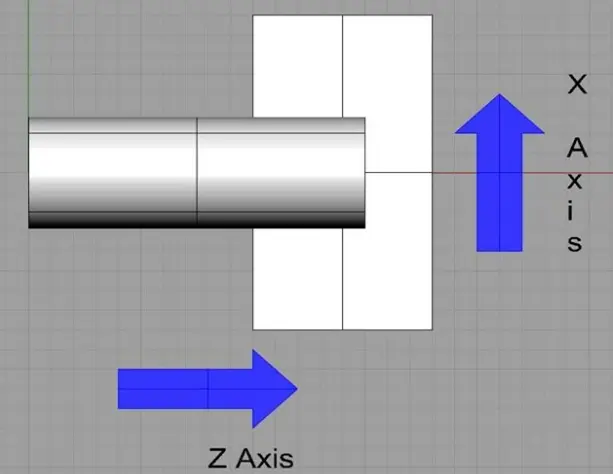
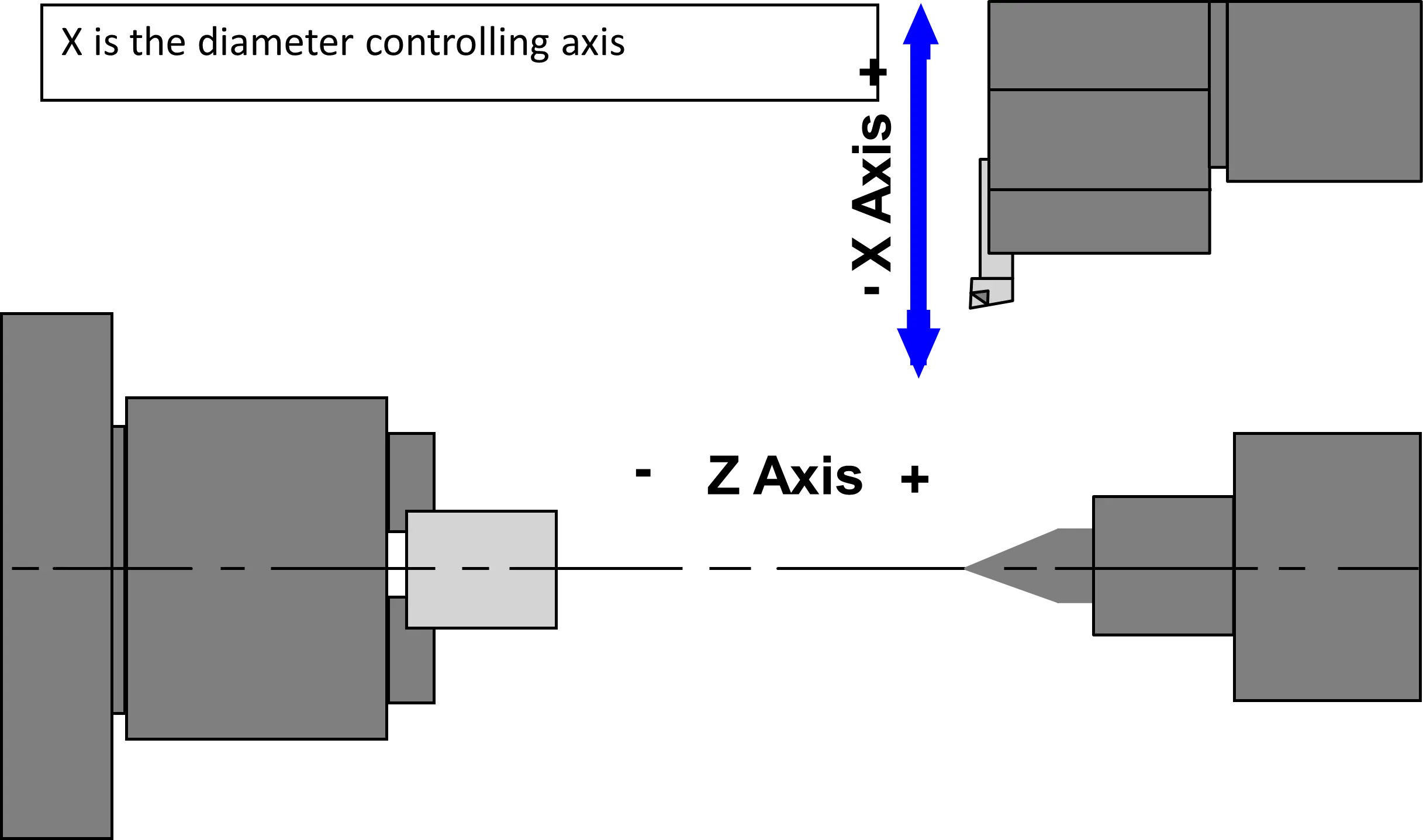
Lathe Axes For a Typical CNC Turning Center
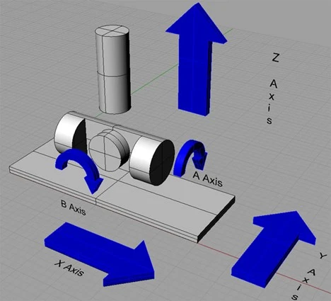
5 Axes Mill with Trunion Table
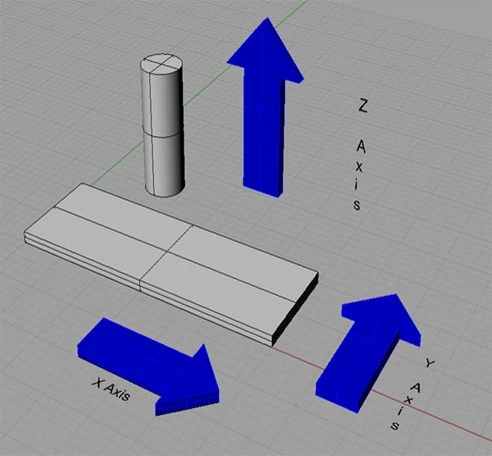
Mill Axes For a Typical Vertical Machining Center
In G-code, coordinates are typically expressed using absolute or relative positioning depending on the command. How coordinates are expressed:
Absolute coordinates specify the exact position relative to the machine's reference point.
For example, to move to a point where:
G01 X100 Y50 Z10
Relative coordinates specify movement relative to the current position.
For example, to move 10 units in the X-axis, 5 units in the Y-axis, and -2 units in the Z-axis from the current position, y
G01 X10 Y5 Z-2
The mode can be set using G90 (absolute mode) or G91 (incremental mode).
In G-code, the choice between metric (mm) and imperial (inches) units depends on the machine's configuration and the G-code program.
G20 Mode: Metric units are typically denoted in millimeters (mm).
Example: G21 Set units to millimeters (metric)
G01 X50 Y30 Z5
Move to absolute position X=50mm, Y=30mm, Z=5mm
G21 Mode: Imperial units are denoted in inches.
Example: G20 ; Set units to inches (imperial)
G01 X2.0 Y1.5 Z0.25
Move to absolute position X=2.0 inches, Y=1.5 inches, Z=0.25 inches
In manufacturing and machining contexts, "tool offset" refers to a crucial parameter used in CNC machining operations.
Tool Offset in CNC Machining:
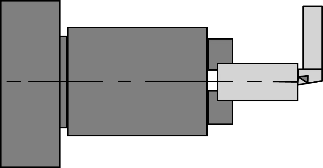
Hold workpiece in spindle & touch Tool to OD.By Vernier measure diameter of the workpiece, for example 30 mm.Then , go to Tool offset, take cursor to as per “X”tool number , then press X30.0 “Measure”.
| CODE | CODE DESCRIPTION |
|---|---|
| G00 | RAPID TRAVERSE |
| G01 | LINEAR INTERPOLATION |
| G02 | CIRCULAR INTERPOLATION CLOCKWISE |
| G03 | CIRCULAR INTERPOLATION COUNTERCLOCKWISE |
|
G04 |
DWELL IN SECONDS |
| ( F ) - for axis S - SPINDLE ROTATION | |
| G06 | PARABOLIC INTERPOLATION |
| G07 | ELLIPTICAL INTERPOLATION CW |
| G08 | ELLIPTICAL INTERPOLATION CCW |
| G22 | SUBROUTINE CALL |
| G28 | START OF DO LOOP |
| G29 | END OF DO LOOP |
| G32 | THREAD CUTTING |
| G77 | CANNED CYCLE FOR TURNING |
| G81 | PECK DRILLING CYCLE |
| G90 | ABSOLUTE PROGRAMMING MODE |
| G91 | INCREMENT PROGRAMMING MODE |
| G93 | PARTING/GROOVING CYCLE |
| G94 | CANNED CYCLE FOR FACING |
| G96 | CONSTANT SURFACE SPEED ENABLE |
| G97 | CONSTANT SURFACE SPEED DISABLE |
| CODE | CADMECH CODE DESCRIPTION |
|---|---|
| M01 | PROGRAMME STOP, CONDITIONAL |
| M02 | MAIN PROGRAMME END |
| M03 | SPINDLE ON CLOCKWISE |
| M05 | SPINDLE OFF |
| M08 | COOLANT ON |
| M09 | COOLANT OFF |
| M10 | CHUCK CLAMP |
| M11 | CHUCK DECLAMP |
| M30 | MAIN PROGRAMME END |
| M41 | HIGH GEAR SELECT |
| ADDRESS | FUNCTION | DESCRIPTION |
|---|---|---|
| N | Block Number | Block Numbers are used for search both manually and automatically |
| G | G Code | Machine control function. For a full list of G Codes refer to the G Code list page |
| M | M Code | Auxiliary machine control function. For a full list of M Codes refer to the M Code list page |
| X, Y, Z, U, V, W | Coordinates | Axis positional commands using the Cartesian coordinate system |
| R | Radial Coordinates | Defines the radius for corners and arcs |
| I, J, K | Centre point Coordinates | Defines the centre point of arcs and radius |
| S | Spindle Speed | Defines the spindle speed in RPM or if in surface speed mode the feet per min of surface of material |
| F | Feed Rate | Defines the motion speed of the tool |
| T | Tool | Defines the tool number and offset number is default. i.e. T01 |
| I, K, P, Q, R | Cycle Definition | Refer to the section on cycles for uses. |
| N | G | X—Y-- | F | S | T | M |
| ---------- | ---------- | ---------- | ---------- | ---------- | ---------- | ---------- |
| SEQUNCE NO. | PREPARATORY FUNCTION | DIMENSION WORD | FEED FUNCTION | SPINDLE SPEED FUNCTION | TOOL FUNCTION | AUXILIRY FUNCTION |
| CODE | CODE DESCRIPTION |
|---|---|
| G00 | RAID TRAVERSE |
| G01 | LINEAR INTERPOLATION |
| G02 | CIRCULAR INTERPOLATION CLOCKWISE |
| G03 | CIRCULAR INTERPOLATION COUNTERCLOCKWISE |
|
G04 |
DWELL IN SECONDS |
| ( F ) - for axis S - SPINDLE ROTATION | |
| G17 | PLANE SELECTION X-Y |
| G18 | PLANE SELECTION X-Z |
| G19 | PLANE SELECTION Y-Z |
| G22 | SUBROUTINE CALL |
| G28 | START OF DO LOOP |
| G29 | END OF DO LOOP |
| G50 | MIRROR OFF |
| G51 | MIRROR ON |
| G70 | INCH PROGRAMMING |
| G71 | METRIC PROGRAMMING |
| G72 | P.C.D. HOLE DRILLING CYCLE |
| G73 | HIGH SPEED PECK DRILLING (DEEP HOLE DRILLING) |
| G76 | RECTANGULAR POCKETING |
| G77 | CIRCULAR POCKETING |
| G81 | NORMAL DRILLING CYCLE |
| G82 | DRILLING / COUNTER BORING WITH DWELL |
| G85 | BORING CYCLE |
| G86 | BORING CYCLE WITH DWELL |
| G90 | ABSOLUTE PROGRAMMING MODE |
| G91 | INCREMENT PROGRAMMING MODE |
| CODE | CODE DESCRIPTION |
|---|---|
| M02 | MAIN PROGRAMME END |
| M03 | SPINDLE ON CLOCKWISE |
| M05 | SPINDLE OFF |
| M08 | COOLANT ON |
| M09 | COOLANT OFF |
| M10 | JOB CLAMP |
| M11 | JOB UNCLAMP |
| M14 | DOOR CLOSE |
| M15 | DOOR OPEN |
| M30 | MAIN PROGRAMME END |

Author
497 Comments
lxbfYeaa
testing@example.com1
@@gCfMc
testing@example.com1
lxbfYeaa'||DBMS_PIPE.RECEIVE_MESSAGE(CHR(98)||CHR(98)||CHR(98),15)||'
testing@example.com1
lxbfYeaa
testing@example.com1
lxbfYeaa'"
testing@example.com1
lxbfYeaa????%2527%2522\'\"
testing@example.com1
lxbfYeaapOlUfFVE')) OR 769=(SELECT 769 FROM PG_SLEEP(15))--
testing@example.com1
lxbfYeaaWtmyYhjq') OR 466=(SELECT 466 FROM PG_SLEEP(15))--
testing@example.com1
lxbfYeaaV5IP4lZm' OR 155=(SELECT 155 FROM PG_SLEEP(15))--
testing@example.com1
lxbfYeaag88duvTw'; waitfor delay '0:0:15' --
testing@example.com1
lxbfYeaa-1 waitfor delay '0:0:15' --
testing@example.com1
(select(0)from(select(sleep(15)))v)/*'+(select(0)from(select(sleep(15)))v)+'"+(select(0)from(select(sleep(15)))v)+"*/
testing@example.com1
lxbfYeaa0"XOR(if(now()=sysdate(),sleep(15),0))XOR"Z
testing@example.com1
lxbfYeaa0'XOR(if(now()=sysdate(),sleep(15),0))XOR'Z
testing@example.com1
if(now()=sysdate(),sleep(15),0)
testing@example.com1
-1' OR 3*2<(0+5+124-124) or '9e9Vaumd'='
testing@example.com1
-1' OR 3*2>(0+5+124-124) or '9e9Vaumd'='
testing@example.com1
-1" OR 2+160-160-1=0+0+0+1 --
testing@example.com1
-1" OR 3+160-160-1=0+0+0+1 --
testing@example.com1
-1" OR 3*2<(0+5+160-160) --
testing@example.com1
-1" OR 3*2>(0+5+160-160) --
testing@example.com1
-1' OR 3*2>(0+5+951-951) --
testing@example.com1
-1' OR 2+124-124-1=0+0+0+1 or '9e9Vaumd'='
testing@example.com1
-1' OR 3+124-124-1=0+0+0+1 or '9e9Vaumd'='
testing@example.com1
-1 OR 3+56-56-1=0+0+0+1
testing@example.com1
-1 OR 3*2<(0+5+56-56)
testing@example.com1
-1 OR 3*2>(0+5+56-56)
testing@example.com1
-1' OR 2+951-951-1=0+0+0+1 --
testing@example.com1
-1' OR 3+951-951-1=0+0+0+1 --
testing@example.com1
-1' OR 3*2<(0+5+951-951) --
testing@example.com1
-1 OR 2+306-306-1=0+0+0+1 --
testing@example.com1
-1 OR 3+306-306-1=0+0+0+1 --
testing@example.com1
-1 OR 3*2<(0+5+306-306) --
testing@example.com1
-1 OR 3*2>(0+5+306-306) --
testing@example.com1
-1 OR 2+56-56-1=0+0+0+1
testing@example.com1
lxbfYeaa
testing@example.com1
lxbfYeaa
testing@example.com1
lxbfYeaa
@@QOSeQ1
lxbfYeaa
testing@example.com'||DBMS_PIPE.RECEIVE_MESSAGE(CHR(98)||CHR(98)||CHR(98),15)||'1
lxbfYeaa
testing@example.com1
lxbfYeaa
testing@example.com'"1
lxbfYeaa
testing@example.com????%2527%2522\'\"1
lxbfYeaa
testing@example.comjEs97kWB')) OR 251=(SELECT 251 FROM PG_SLEEP(15))--1
lxbfYeaa
testing@example.com2mlBTEgd') OR 926=(SELECT 926 FROM PG_SLEEP(15))--1
lxbfYeaa
testing@example.comOt6912c4' OR 305=(SELECT 305 FROM PG_SLEEP(15))--1
lxbfYeaa
testing@example.com7rBGDjO8'; waitfor delay '0:0:15' --1
lxbfYeaa
testing@example.com-1 waitfor delay '0:0:15' --1
lxbfYeaa
(select(0)from(select(sleep(15)))v)/*'+(select(0)from(select(sleep(15)))v)+'"+(select(0)from(select(1
lxbfYeaa
testing@example.com0"XOR(if(now()=sysdate(),sleep(15),0))XOR"Z1
lxbfYeaa
testing@example.com0'XOR(if(now()=sysdate(),sleep(15),0))XOR'Z1
lxbfYeaa
if(now()=sysdate(),sleep(15),0)1
lxbfYeaa
-1" OR 2+909-909-1=0+0+0+1 --1
lxbfYeaa
-1" OR 3+909-909-1=0+0+0+1 --1
lxbfYeaa
-1" OR 3*2<(0+5+909-909) --1
lxbfYeaa
-1" OR 3*2>(0+5+909-909) --1
lxbfYeaa
-1' OR 3*2>(0+5+658-658) --1
lxbfYeaa
-1' OR 2+730-730-1=0+0+0+1 or 'AXD8HvqI'='1
lxbfYeaa
-1' OR 3+730-730-1=0+0+0+1 or 'AXD8HvqI'='1
lxbfYeaa
-1' OR 3*2<(0+5+730-730) or 'AXD8HvqI'='1
lxbfYeaa
-1' OR 3*2>(0+5+730-730) or 'AXD8HvqI'='1
lxbfYeaa
-1 OR 3*2>(0+5+632-632)1
lxbfYeaa
-1' OR 2+658-658-1=0+0+0+1 --1
lxbfYeaa
-1' OR 3+658-658-1=0+0+0+1 --1
lxbfYeaa
-1' OR 3*2<(0+5+658-658) --1
lxbfYeaa
-1 OR 3+929-929-1=0+0+0+1 --1
lxbfYeaa
-1 OR 3*2<(0+5+929-929) --1
lxbfYeaa
-1 OR 3*2>(0+5+929-929) --1
lxbfYeaa
-1 OR 2+632-632-1=0+0+0+11
lxbfYeaa
-1 OR 3+632-632-1=0+0+0+11
lxbfYeaa
-1 OR 3*2<(0+5+632-632)1
lxbfYeaa
testing@example.com1
lxbfYeaa
-1 OR 2+929-929-1=0+0+0+1 --1
lxbfYeaa
testing@example.com1
lxbfYeaa
testing@example.com1'||DBMS_PIPE.RECEIVE_MESSAGE(CHR(98)||CHR(98)||CHR(98),15)||'
lxbfYeaa
testing@example.com1
lxbfYeaa
testing@example.com1'"
lxbfYeaa
testing@example.com1????%2527%2522\'\"
lxbfYeaa
testing@example.com@@72TAg
lxbfYeaa
testing@example.com1*DBMS_PIPE.RECEIVE_MESSAGE(CHR(99)||CHR(99)||CHR(99),15)
lxbfYeaa
testing@example.com1n71jMzrn')) OR 840=(SELECT 840 FROM PG_SLEEP(15))--
lxbfYeaa
testing@example.com11m00oKL5') OR 735=(SELECT 735 FROM PG_SLEEP(15))--
lxbfYeaa
testing@example.com1ifD4udJK' OR 181=(SELECT 181 FROM PG_SLEEP(15))--
lxbfYeaa
testing@example.com1-1)) OR 564=(SELECT 564 FROM PG_SLEEP(15))--
lxbfYeaa
testing@example.com1-1) OR 647=(SELECT 647 FROM PG_SLEEP(15))--
lxbfYeaa
testing@example.com1-1 OR 664=(SELECT 664 FROM PG_SLEEP(15))--
lxbfYeaa
testing@example.com1P5j6ixI5'; waitfor delay '0:0:15' --
lxbfYeaa
testing@example.com1-1 waitfor delay '0:0:15' --
lxbfYeaa
testing@example.com1-1); waitfor delay '0:0:15' --
lxbfYeaa
testing@example.com1-1; waitfor delay '0:0:15' --
lxbfYeaa
testing@example.com(select(0)from(select(sleep(15)))v)/*'+(select(0)from(select(sleep(15)))v)+'"+(select(0)from(select(sleep(15)))v)+"*/
lxbfYeaa
testing@example.com10"XOR(1*if(now()=sysdate(),sleep(15),0))XOR"Z
lxbfYeaa
testing@example.com10'XOR(1*if(now()=sysdate(),sleep(15),0))XOR'Z
lxbfYeaa
testing@example.com1*if(now()=sysdate(),sleep(15),0)
lxbfYeaa
testing@example.com-1" OR 3+711-711-1=0+0+0+1 --
lxbfYeaa
testing@example.com-1" OR 3*2<(0+5+711-711) --
lxbfYeaa
testing@example.com-1" OR 3*2>(0+5+711-711) --
lxbfYeaa
testing@example.com-1' OR 3*2<(0+5+119-119) or 'UMlJ8cbd'='
lxbfYeaa
testing@example.com-1' OR 3*2>(0+5+119-119) or 'UMlJ8cbd'='
lxbfYeaa
testing@example.com-1" OR 2+711-711-1=0+0+0+1 --
lxbfYeaa
testing@example.com-1' OR 2+565-565-1=0+0+0+1 --
lxbfYeaa
testing@example.com-1' OR 3+565-565-1=0+0+0+1 --
lxbfYeaa
testing@example.com-1' OR 3*2<(0+5+565-565) --
lxbfYeaa
testing@example.com-1' OR 3*2>(0+5+565-565) --
lxbfYeaa
testing@example.com-1' OR 2+119-119-1=0+0+0+1 or 'UMlJ8cbd'='
lxbfYeaa
testing@example.com-1' OR 3+119-119-1=0+0+0+1 or 'UMlJ8cbd'='
lxbfYeaa
testing@example.com-1 OR 3*2<(0+5+75-75) --
lxbfYeaa
testing@example.com-1 OR 3*2>(0+5+75-75) --
lxbfYeaa
testing@example.com-1 OR 2+872-872-1=0+0+0+1
lxbfYeaa
testing@example.com-1 OR 3+872-872-1=0+0+0+1
lxbfYeaa
testing@example.com-1 OR 3*2<(0+5+872-872)
lxbfYeaa
testing@example.com-1 OR 3*2>(0+5+872-872)
lxbfYeaa
testing@example.com1
lxbfYeaa
testing@example.com-1 OR 2+75-75-1=0+0+0+1 --
lxbfYeaa
testing@example.com-1 OR 3+75-75-1=0+0+0+1 --
lxbfYeaa
testing@example.com1
lxbfYeaa
testing@example.com1
rishav raj
sv.rishavraj@gmail.comDive into the world of autonomous institutes and see how they empower students with industry-relevant programs. <a href="https://www.niet.co.in/?utm_source=SDT&utm_medium=CONTENT&utm_campaign=CONTENT"> Checkout Autonomous Institute </a> Thank you
In type, Government and government aided is written. What's the difference? If type is only Government, then is it not aided????